Blog
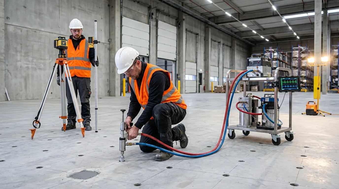
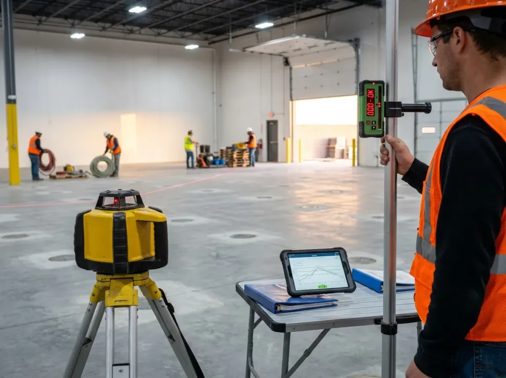
Polyurethane concrete lifting crew executing staged injection on a commercial slab with laser level monitoring and a grid of visible injection ports

The Concrete Lifting Process: Step-by-Step Guide to What Happens

webdev | 27 Jul 2026

A polyurethane concrete lifting project follows a standard eight-step process: pre-lift condition assessment, void investigation and documentation, port layout and spacing, port drilling, material setup and preparation, staged injection with real-time elevation monitoring, port finishing, and post-lift verification with closeout documentation. Standard commercial projects complete in a single work window; industrial and municipal projects span multiple days depending on area, void volume, and lift complexity. Return-to-service for light loading is typically within one hour of injection completion.

Facility managers, procurement officers, and plant engineers frequently want to know exactly what happens on a polyurethane concrete lifting project, from the pre-injection walk to the crew loading equipment back into the truck. This article documents the standard process step by step, with what the owner should see, what the crew should be doing, and what should trigger concern at each phase. It applies to commercial, industrial, and municipal projects; the process is the same across all three with different documentation and scope.

Step 1: Pre-Lift Condition Assessment

Before the injection rig arrives on site, a qualified specialty contractor conducts a pre-lift condition assessment. This is the walk that determines whether polyurethane concrete lifting is the right scope at all. Elements of a proper assessment:

  • Visual survey of the slab surface: cracking, joint condition, moisture penetration, spalling, patching history
  • Elevation survey with laser level or transit, mapping the current surface profile and quantifying the settlement extent relative to design or adjacent reference elevations
  • Sounding for delamination using dragged chain or hammer sounding to identify hollow areas
  • Drainage inspection to identify stormwater or utility water sources that may have contributed to the settlement
  • Load history review to understand what the slab has carried and any changes in loading pattern
  • Photographic documentation from multiple angles

The assessment concludes with a recommendation. Polyurethane lifting is appropriate when the concrete itself is structurally sound and the failure is in the subgrade. When the concrete has itself failed, an honest contractor recommends replacement or structural repair rather than injection; those conditions are covered under foundation issues.

What the owner should see: the contractor spending 30 minutes to 2 hours on the site walk depending on project size, documenting observations, asking about slab history, drainage, and load, and providing a written assessment before quoting scope. A contractor who quotes injection over the phone without a site walk has skipped this step.
Step 2: Void Investigation and Documentation

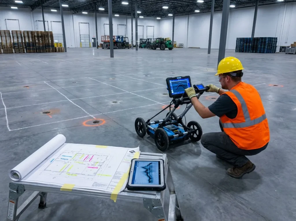
Technician operating a ground-penetrating radar unit on a commercial concrete slab during pre-lift void investigation with real-time subsurface data visible on the GPR display

Once the assessment identifies polyurethane lifting as the appropriate scope, the next step is confirming what's actually under the slab. Investigation methods:

  • Ground-penetrating radar (GPR). A wheeled GPR unit is guided across the slab in a grid pattern, and the display shows real-time subsurface reflections indicating voids, changes in soil density, and buried utilities. GPR is the primary void investigation tool for commercial, industrial, and municipal projects.
  • Boroscope confirmation. A small-diameter borehole is drilled through the slab and a fiber-optic camera is inserted to visually confirm void extent and depth.
  • Elevation-differential mapping. The pre-lift elevation survey identifies the extent of settlement, which correlates with the location of subgrade support failure.
  • Utility locate confirmation. 811 utility locate service is called before any drilling. Confirmed marks for gas, water, sewer, telecom, and electric utilities are added to the site plan.

The output is a documented understanding of where the subgrade support has failed and to what extent, mapping the subsurface voids that drive port layout in the next step.

What the owner should see: a marked-up site plan showing sweep patterns, identified voids, utility locations, and planned port layout. Verbal confirmation of void findings without written documentation is not adequate for commercial or municipal work.

Step 3: Port Layout and Spacing

The port layout is the pattern of drilling locations across the slab. Layout is determined by slab thickness and reinforcement pattern, void extent and depth from the investigation, slab dimensions and joint locations, access constraints, and load transfer requirements. Ports are typically placed at 2 to 4 foot spacing along the primary axis, with additional ports at slab corners and near joints where differential lift risk is highest.

The layout is marked directly on the slab surface with paint or chalk before drilling begins. For commercial and municipal projects, the layout is also recorded on the site plan for closeout documentation.

What the owner should see: the marked layout on the slab, with a visible grid or pattern that reflects the void map and slab dimensions. Random or arbitrary port placement is a red flag.

Step 4: Port Drilling

Injection ports are drilled through the slab using rotary hammer drills with dust collection attachments. Standard port diameter is 5/8 inch. Drill depth is typically to the underside of the slab plus a small tolerance to ensure the port fully penetrates into the void space.

Drilling proceeds systematically across the marked layout, with each port confirmed to have reached the subgrade before moving to the next. Cored slugs are cleared, and each port is temporarily plugged to prevent contamination while the layout is completed.

Dust collection is critical for indoor and enclosed environments. Modern drills use HEPA-rated vacuum attachments that capture concrete dust at the drill bit. This is both an OSHA respirable dust concern and an operational concern for facility hygiene.

What the owner should see: clean drilling with visible dust collection, systematic progression across the layout, and each completed port temporarily plugged. Dust clouds in the work area indicate inadequate dust control.

Step 5: Material Setup and Preparation

The injection rig is prepared before injection begins:

  • Component drums (A and B) are staged with proper insulation and drum warmers if ambient temperature warrants preconditioning
  • The proportioning pump is calibrated to the specified A:B ratio and pressure
  • Heated hose packs are warmed to the manufacturer-specified operating temperature range (typically 100 to 140°F at the mixing head)
  • The mixing-head injection gun is fitted with a fresh mixing tip appropriate for the specified formulation
  • A test-cure sample is generated at the beginning of the work day to confirm the material is reacting to specification
  • PPE is in place: applicator respiratory protection, gloves, and skin coverage

For projects requiring specific formulations (density grade, hydrophobic vs hydrophilic, fast-set vs standard), the correct formulation is confirmed against the specification and the manufacturer certificate of analysis for the batch in use.

What the owner should see: deliberate setup activity taking 30 minutes to an hour before injection begins, temperature readings on component drums and hose packs, a test-cure sample being observed, and clear PPE compliance. A crew that begins injection without a visible setup phase is skipping steps.

Step 6: Staged Injection with Real-Time Elevation Monitoring

Injection is the core operation, executed in controlled stages:

  • First-stage injection delivers a metered volume of foam per port, typically 10 to 25 percent of the estimated void volume, at controlled pressure
  • Elevation is monitored continuously using a rotary laser level or manometer at multiple slab locations; as the foam expands, elevation changes are measured and recorded in real time
  • Successive stages deliver additional foam based on the observed lift response, each stage smaller than the initial injection to control differential lift and avoid over-lifting
  • Cross-port coordination ensures adjacent ports are worked in a sequence that produces uniform lift rather than localized humps
  • Pressure and volume telemetry per port is recorded in the daily injection log

For projects with lift targets, the crew stops injection at each port when the target elevation is reached or when the elevation stops responding to additional material. For void fill projects without lift targets, injection continues until the void is confirmed filled by pressure and volume analysis.

The injection phase for a commercial warehouse slab bay is typically 4 to 8 hours. For a bridge approach slab, 4 to 8 hours per bay executed as staged lane-by-lane work. Complex or larger projects span multiple days.

What the owner should see: measured, deliberate injection with active elevation monitoring, not "pump and pray." Real-time laser level or manometer reading is visible; the crew is coordinating verbally between injection gun and monitor; per-port volumes are being recorded. Chaotic injection or lack of monitoring is a red flag.

Step 7: Port Finishing

Once injection is complete and the foam has reached tack-free time (typically 5 to 15 minutes per port), port finishing proceeds:

  • Excess cured foam is trimmed flush with the slab surface using hand tools
  • The port is filled with a color-matched polymer or cementitious patching compound
  • The patch is troweled flush with the surrounding slab surface
  • Weathered slabs may receive additional color match or acid etching to blend the patch with surrounding aged concrete

For high-visibility slabs (entry approaches, plaza slabs, public walkways) the finishing quality is more important than for back-of-house industrial slabs. Owners should specify the finish standard in the contract and inspect the completed patches before final acceptance.

What the owner should see: patched ports flush with the slab surface and reasonably matched to the surrounding color and texture. Rough patches, unfilled ports, or excessive proud material is not acceptable finish quality.
Step 8: Post-Lift Verification and Closeout Documentation

Technician conducting a final elevation survey with a rotary laser level and elevation rod on a completed polyurethane lifted slab, generating the post-lift verification record

The final step is verification and documentation:

  • Post-lift elevation survey documents the final slab profile. For lift projects, the survey confirms the target elevation was achieved within tolerance. For void fill projects, it confirms the slab remained at the original elevation.
  • Injection log reconciliation compares planned material volume against actual volume used, with significant variance explained in a variance note.
  • Photo documentation captures the completed slab from multiple angles.
  • Post-injection boroscope confirmation (for commercial and municipal projects) verifies the foam has filled the intended void space at representative sample locations.
  • Return-to-service authorization is provided in writing based on the material's compressive strength development curve. Light loading is typically permitted within 1 hour; heavy loading may require 24 hours per the product TDS.
  • Closeout documentation package is compiled and delivered to the owner: daily injection log, pre- and post-elevation surveys, photo documentation, material traceability records, planned vs actual reconciliation, contractor completion report with engineer acceptance signature (for commercial and municipal work), and as-built drawings showing injection zones.

What the owner should see: a formal closeout handoff, a complete written documentation package (not a verbal summary), a walk-through of the completed work with the crew lead, and written return-to-service authorization referencing the product TDS.

What Should Trigger Concern During Execution

Certain patterns should trigger the owner to pause the work and ask questions:

  • Injection without elevation monitoring: if no laser level or manometer is visible, the crew cannot control lift
  • Rapid injection without stops: continuous high-volume injection at a single port risks over-lifting and slab cracking
  • Visible slab cracking during injection: new cracks forming during work indicate over-pressurization
  • Foam escaping at joints or existing cracks: substantial escape indicates the injection is not reaching intended void space
  • Missing or unclear documentation: no injection log, no elevation readings, no material lot numbers
  • PPE non-compliance: absence of a respirator during injection is an immediate safety concern

A contractor exhibiting these patterns is not operating at infrastructure rigor. Where the concrete itself has failed rather than the subgrade, the correct scope is structural repair of the foundation issues rather than injection.

Return-to-Service Sequence

Once injection and finishing are complete, return to service depends on the loading class:

  • Foot traffic. Immediately after tack-free (5 to 15 minutes after port injection).
  • Light vehicle loading. Typically 1 hour after injection completion for standard hydrophobic 4-lb foam.
  • Medium commercial loading (light trucks, forklifts under 5,000 lb capacity). Typically 4 to 8 hours per manufacturer TDS.
  • Heavy commercial loading (loaded forklifts, delivery trucks, industrial equipment). Typically 24 hours per manufacturer TDS unless an accelerated formulation was specified.
  • Full design load (heavy industrial, DOT vehicle loading). Per manufacturer TDS and engineer-of-record authorization.

The compressive strength development curve on the product TDS is the authoritative source. Wall-clock time is a proxy; strength development is the actual gate.

Key Takeaways

  • The eight-step process (assessment, investigation, layout, drilling, setup, injection, finishing, verification) is standard across commercial, industrial, and municipal projects.
  • Pre-lift condition assessment and void investigation together determine whether polyurethane lifting is the right scope. Skipping these steps is a red flag.
  • Port drilling uses 5/8-inch diameter with dust collection; the layout reflects the void map and slab dimensions.
  • Material setup is deliberate; component preconditioning, pump calibration, and a test-cure sample are baseline items.
  • Staged injection with continuous real-time elevation monitoring is what controls lift accuracy. Uncontrolled injection risks over-lifting and slab damage.
  • Port finishing quality matters more on visible surfaces than on back-of-house industrial slabs.
  • Closeout documentation is the record that supports warranty claims, asset management, and future inspection.
  • Return-to-service loading is governed by the material's compressive strength development curve, not wall-clock time.
  • Owners should see organized, documented, deliberate work at every step. Rushed or undocumented work warrants a work stoppage and a conversation with the contractor.

Conclusion

The polyurethane concrete lifting process is not a mystery. Each of the eight steps has a defined purpose, standard tools, and observable characteristics. Owners who understand the process can procure it competently, monitor it during execution, and accept the closeout documentation with confidence that the work meets the specification. Owners who do not understand the process are relying on the contractor to fill in that judgment on their behalf.

To scope a polyurethane concrete lifting project on a commercial, industrial, or municipal property in the Houston metro, schedule a site assessment.


Author

Marcus Trevino is a Senior Infrastructure Remediation Specialist at Superior PolyLift in Houston, TX, with 18+ years of experience solving complex concrete lifting and foundation stabilization problems for commercial, municipal, and industrial clients.

FAQs
Commercial warehouse slab bay: 4 to 8 hours. Bridge approach slab: 4 to 8 hours per bay. Municipal sidewalk panel: 1 to 2 hours per panel. Complex or larger projects span multiple days. Return-to-service for light loading is typically within one hour of injection completion.
Yes. For commercial and light industrial projects the owner's representative commonly observes the work directly. For industrial and municipal projects the facility manager, engineer, or inspector is typically on site. Owners should stay outside the immediate work zone during injection for safety and coordinate observation timing with the crew lead.
811 utility locate service is called before any drilling. Confirmed marks for gas, water, sewer, telecom, and electric utilities are added to the port layout plan, and ports are placed to avoid conflicts. For high-risk utility zones, additional confirmation methods (GPR, hand-dug potholing) may be used. A contractor who begins drilling without confirmed utility locates should not be on site.
Properly controlled injection with staged loading and elevation monitoring does not cause additional cracking. Small pre-existing cracks may open slightly during injection and close after cure. Over-pressurization or uncontrolled injection can cause new cracks, which is why staged injection with continuous monitoring is standard practice.
Volume depends on the void extent identified during investigation, the lift target if any, and slab dimensions. The estimate from the contractor should include volume, and the closeout documentation should reconcile planned vs actual. Significant variance is explained in a variance note.
Foot traffic is safe immediately after tack-free time. Light vehicle loading is typically permitted 1 hour after injection completion for standard hydrophobic 4-lb foam. Heavier loading requires longer per the product TDS. Return-to-service authorization is documented in the closeout package.
The closeout documentation is the record. Pre- and post-elevation surveys confirm the lift target was achieved. The injection log confirms controlled staged injection with monitoring. Boroscope confirmation (on commercial and municipal work) verifies the void was filled. A contractor unable to provide this documentation cannot verify that the work meets the specification.
The injected foam is not readily removable once cured, which is what makes it a durable repair. If the slab is later replaced, the removal work becomes part of the replacement scope. When execution problems occur, they typically require targeted remediation (additional injection at specific locations, patching, or in extreme cases slab replacement) rather than removal of the original injection.
Find Out How We Can Engineer a Solution For You
Superior Polylift Logo
A Division of Superior Grouting
crossmenu linkedin facebook pinterest youtube rss twitter instagram facebook-blank rss-blank linkedin-blank pinterest youtube twitter instagram Skip to content