Engineers control foam expansion through real-time pressure monitoring, precise density calculations, strategic injection sequencing, and temperature management to achieve exact void filling without over-expansion or structural damage.
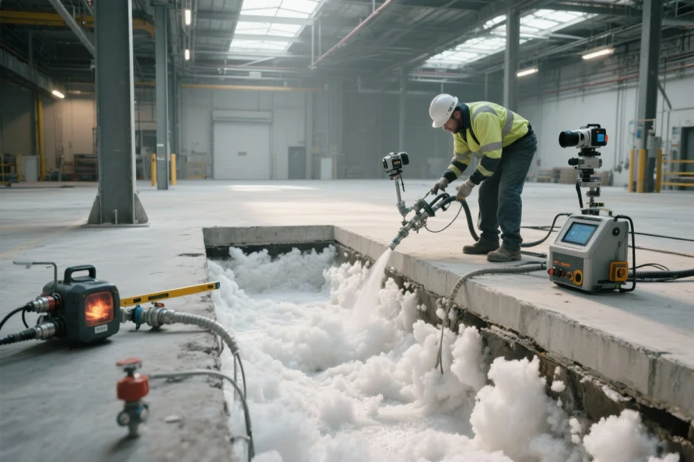
Polyurethane foam injection addresses critical subsurface voids in municipal and industrial infrastructure, but success depends on controlling expansion rates. Uncontrolled foam expansion cracks dam foundations, displaces tunnel linings, or fails to fill voids completely beneath treatment plant structures.
Professional void filling requires engineering controls that manage chemical reactions, predict expansion behavior, and adjust injection parameters in real-time. This analysis examines the technical systems, calculations, and quality protocols that ensure foam fills infrastructure voids precisely without causing structural damage to dams, levees, tunnels, or water treatment facilities.
| Parameter | Optimal Range | Impact on Infrastructure Void Filling | Monitoring Method |
| Component Temperature | 65-85°F | Controls reaction speed and expansion rate; deviations cause unpredictable expansion in confined tunnel voids or dam foundation spaces, potentially compromising structural integrity of critical infrastructure | Temperature sensors at proportioning unit mixing chamber with automatic heating/cooling systems and continuous data acquisition recording every 5 seconds |
| Injection Pressure | 5-20 psi (application dependent) | Indicates void filling progress; sudden pressure increases signal boundary contact in tunnel voids while sustained low pressure indicates interconnected void networks beneath levee structures requiring additional material | Pressure transducers at injection manifolds providing digital readouts updated every 2 seconds with programmable threshold alarms for infrastructure protection |
| Expansion Ratio | 15:1 to 40:1 | Determines final foam density and load-bearing capacity; lower ratios (15:1-20:1) create dense foam for high-load dam foundations while higher ratios (30:1-40:1) fill non-structural voids in utility tunnels | Pre-calculated based on polyurethane formulation chemistry; verified through ASTM D1622 density testing of extracted core samples from infrastructure installations |
| Substrate Temperature | 40-95°F | Affects foam adhesion to concrete and cure rate; cold tunnel walls (below 50°F) slow surface reactions while hot summer conditions (above 90°F) in uncovered structures accelerate premature skinning | Infrared thermometers or contact temperature probes measuring concrete surface temperature at multiple injection zone locations before operations commence |
| Flow Rate | 3-10 gallons/minute | Controls expansion speed and working time in large infrastructure voids; faster rates reduce labor time but risk premature setting in extended void networks beneath treatment plants | Positive displacement flow meters integrated with proportioning equipment providing real-time volumetric data and cumulative totals for quality documentation |
Polyurethane foam expansion begins when two liquid components—polyol resin and polymeric isocyanate—combine through high-pressure impingement mixing and trigger an exothermic chemical reaction. This reaction generates carbon dioxide gas that creates cellular foam structure while polymer chains cross-link into a rigid matrix.
Critical factors affecting expansion behavior in infrastructure applications:
Engineers conduct comprehensive site assessments measuring substrate temperatures in tunnel sections, determining void configurations through ground-penetrating radar or acoustic testing, and selecting foam formulations matched to infrastructure conditions.
The expansion ratio—liquid volume injected versus final foam volume—serves as the primary control parameter. A 20:1 expansion ratio produces twenty cubic feet of foam from one cubic foot of liquid chemicals. Engineers select ratios based on required density: higher ratios create lighter foam for non-structural void filling in utility tunnels, while lower ratios produce denser foam providing load-bearing support for dam foundations and spillway structures.
Precise quantity calculations prevent material waste and incomplete void filling in large infrastructure installations. Engineers determine void volume using ground-penetrating radar surveys of dam foundations, acoustic testing in tunnel sections, or hydraulic pressure testing in levee structures. Calculations include 10-15% contingency factors accounting for void irregularities, concrete porosity, and interconnected void networks.
Required final foam density specifications for infrastructure applications:
The calculation determines liquid volume:
Liquid Volume Required = (Void Volume × Contingency Factor) ÷ Expansion Ratio
For infrastructure applications, filling a 500 cubic foot void beneath a treatment plant clarifier with 18:1 expansion foam using 12% contingency requires 31.1 gallons of liquid polyurethane. Engineers perform zone-by-zone calculations for dam foundation sections, tunnel segments, and levee structures, creating detailed material specifications ensuring adequate supply for project completion.
Modern polyurethane injection systems incorporate pressure monitoring providing real-time feedback during infrastructure void filling. Pressure transducers measure hydraulic resistance as foam expands into voids beneath dam foundations or within tunnel liner gaps.
Key monitoring parameters tracked by data acquisition systems:
Operators establish pressure thresholds before injection based on substrate strength and void configuration. For dam foundation voids, maximum expansion pressure typically remains below 8-12 psi preventing concrete displacement. For tunnel void filling behind structural linings, pressures may reach 15-20 psi without compromising integrity.
Advanced data acquisition systems log complete injection parameters at 2-5 second intervals. Engineers review logged data verifying proper void filling, diagnosing anomalies indicating unexpected void configurations, and providing documentation for infrastructure project quality assurance records. Pressure monitoring detects larger-than-estimated voids—if foam continues flowing at low pressure beyond calculated volumes, operators recognize additional void space exists in interconnected foundation sections and adjust injection quantities maintaining complete filling.
Temperature profoundly affects polyurethane foam expansion, making thermal control essential for infrastructure void filling precision. Chemical component temperature directly influences reaction kinetics. Manufacturers specify optimal temperatures (typically 70-80°F) producing rated expansion ratios and working times.
Professional injection equipment thermal management systems:
Substrate temperature challenges in infrastructure void filling:
Cold concrete in underground tunnels (below 50°F) slows foam expansion at substrate interfaces while foam cores continue expanding normally, creating density gradients and potentially weakening adhesion. Engineers compensate selecting cold-weather polyurethane formulations with modified catalyst systems maintaining reactivity at reduced temperatures, or scheduling operations during warmer periods when tunnel temperatures moderate.
Hot concrete in uncovered summer conditions (above 90°F) accelerates surface reactions causing premature foam skinning that traps unreacted chemicals beneath surface layers. Engineers address hot substrate conditions using slower-reacting formulations with extended cream times, injecting in controlled volume increments allowing heat dissipation between applications, or scheduling operations during cooler morning periods before concrete temperatures peak.
Filling extensive void networks in dam foundations, levee structures, or treatment plant installations requires strategic injection sequencing controlling pressure distribution and ensuring complete filling throughout infrastructure systems.
Sequential injection prevents critical problems in large-scale applications:
Engineers develop injection plans dividing large voids into manageable zones, injecting foam in calculated sequences, and allowing partial polymerization between stages. Engineers develop sequences by mapping void geometry and identifying strategic injection locations. Peripheral zones receive foam first, working toward central areas preventing foam from blocking access to remote sections.
Critical waiting periods between injection stages:
Specific timing depends on formulation chemistry, substrate temperature in tunnels or dam structures, and target foam density. For extensive infrastructure projects, multiple injection crews work simultaneously in different foundation sections or tunnel zones. This requires coordination ensuring injection sequences avoid pressure conflicts or forcing foam into unprepared areas.
Confirming injected foam achieved specified density throughout filled infrastructure voids ensures structural performance. Core sampling provides direct verification. After complete polymerization (typically 24-48 hours depending on substrate temperature), technicians extract core samples using rotary diamond drilling at specified locations in dam foundations, tunnel floors, or treatment plant structures.
Laboratory testing procedures for infrastructure quality assurance:
Testing protocols specify sampling frequencies based on infrastructure project scale and criticality. Small projects under 1,000 cubic feet require minimum 5 core samples. Medium projects (1,000-5,000 cubic feet) require samples at 8% of injection points with minimum 8 samples. Large infrastructure projects exceeding 5,000 cubic feet require samples at 5% of injection points with minimum 12 samples. Critical dam foundation or levee projects require additional sampling at all high-load transfer zones regardless of project size.
Alternative verification methods for infrastructure applications:
Nuclear density gauge testing offers non-destructive verification using backscatter radiation measuring in-place density without core extraction. Ground-penetrating radar conducted post-injection compares results to pre-injection void mapping, with uniform radar signatures indicating consistent foam density throughout infrastructure foundations.
Engineers establish acceptance criteria requiring average density within ±8% of specified target, individual test results within ±12% of target, and zero readings below minimum acceptable density (typically 90% of target for critical infrastructure). Failed results trigger remedial procedures including supplemental foam injection through new access points drilled into deficient zones, with quantities calculated based on density deficiencies and affected volumes.
| Challenge | Root Cause | Engineering Solution |
| Foam migration into unintended areas | Interconnected void networks in dam foundations or fractures in tunnel concrete allowing preferential flow paths | Install temporary grout curtains isolating injection zones, reduce injection rates to 40% of standard flow allowing controlled expansion, monitor adjacent areas with observation ports |
| Insufficient penetration in remote void sections | Foam following least-resistance paths in complex levee foundation geometries leaving distant sections unfilled | Establish secondary injection points at 12-15 foot spacing targeting remote zones, switch to lower-expansion formulations (15:1 ratio) maintaining flowability through extended void networks |
| Excessive pressure affecting adjacent structures | Injection rate exceeding void acceptance capacity in confined tunnel spaces or foam volume surpassing actual void size | Implement staged injection filling 20% of estimated volume per cycle with 20-minute monitoring intervals, install pressure relief ports in non-critical concrete sections if structurally acceptable |
| Density stratification in vertical voids | Temperature gradients in deep dam foundation voids or inconsistent component mixing in high-volume applications | Pre-condition substrate temperatures using circulated warm air systems, verify proportioning equipment maintains ±2% ratio accuracy through regular calibration, limit individual injection lifts to 8-10 vertical feet |
| Premature reaction in transfer lines | Elevated component temperatures in summer conditions or excessive transfer distances from proportioning unit to injection points in large infrastructure sites | Implement component chilling to 65-68°F before injection, reduce transfer hose lengths below 100 feet using multiple proportioning unit positions, increase pump output pressure reducing chemical residence time in hoses |
Cold weather infrastructure projects create expansion control difficulties. Polyurethane reactions slow significantly below 45°F, extending working times but potentially preventing complete cure before overnight temperature drops. Solutions include cold-weather formulations with modified catalyst packages maintaining reactivity below 40°F, substrate pre-warming using diesel-fired heaters or steam injection raising concrete temperatures above 55°F, temporary environmental enclosures maintaining minimum 50°F ambient temperatures, and scheduling critical operations during peak daily temperatures with extended cure monitoring.
Hot weather conditions in uncovered dam or levee structures accelerate reactions causing rapid foam setting. Engineers select extended cream-time formulations providing 45-60 second working windows, implement component cooling to 62-68°F compensating for hot concrete substrates, inject in reduced volume increments (25% of zone capacity) with cooling intervals, and schedule operations during early morning hours before concrete surface temperatures exceed 85°F.
Infrastructure void filling follows established standards ensuring expansion control, quality assurance, and structural performance.
Critical standards governing infrastructure polyurethane foam applications:
Project specifications reference specific ASTM methodologies establishing acceptance criteria. Infrastructure projects typically specify minimum compressive strength of 50-80 psi at 10% deformation per ASTM D1621 for structural void filling, minimum adhesion strength of 30 psi per ASTM D2126 for dam foundation applications, and target density of 4-6 lb/ft³ per ASTM D1622 for high-load infrastructure support.
Manufacturer technical data provides formulation-specific parameters engineers use for expansion calculations. Data sheets specify optimal component temperature ranges, recommended proportioning equipment operating pressures (typically 1,200-2,000 psi for high-pressure impingement mixing), expected cure schedules at various substrate temperatures, and compressive strengths at different densities and cure durations.
Industry protocols for infrastructure project quality assurance:
Precision void filling in critical infrastructure depends on engineering systems controlling polyurethane foam expansion. Modern proportioning equipment and data acquisition systems provide real-time monitoring enabling instant response to deviation from predicted expansion behavior in dam foundations, tunnel structures, and treatment plant installations.
Sequential injection protocols manage extensive void networks in levee structures and spillway foundations by limiting hydraulic pressure accumulation and verifying complete filling in each zone before advancing. Temperature management systems maintain predictable expansion regardless of seasonal conditions affecting underground tunnel environments or exposed dam structures.
Quality verification through core sampling per ASTM D1622, nuclear density testing, and ground-penetrating radar confirmation ensures completed infrastructure installations meet structural performance specifications. Professional contractors combine advanced proportioning technology, comprehensive operator certification programs, and systematic quality protocols delivering precision void filling supporting critical municipal and industrial infrastructure.For expert void filling services in critical infrastructure applications, contact Superior PolyLift.
Explore how our expertise can benefit your project. Reach out to our team for a consultation and discover the best solutions for your needs.
At Superior PolyLift™, integrity and reliability are the core of our ethos. Our expert team crafts custom solutions that guarantee quality and durability for every project. Choose us for geotechnical excellence that endures.
Copyright © All rights reserved. 2024 • Terms of Use and Privacy Policy • Internet Marketing by Authority Solutions®